KeebMaker Corne Build Guide
Hello there! You’ve found the build guide for KeebMaker’s iteration of the Corne, inspired by the great Foostan! This guide will walk you through the process of soldering and assembling your very own Corne keyboard. This guide applies to both the Cherry (MX) and Low-Profile (Choc) versions of the Corne.
The soldering process for the KeebMaker Corne Keyboard is identical to Foostan’s, with just a couple key differences.
- The KeebMaker Corne exclusively supports the much-easier-to-solder SK6812 Mini-E LEDs for the per-key lighting rather than the tricky SK6812 Minis. These LEDs have legs that hold them in place and make them a cinch to solder.
- Both the Cherry (MX) and Low-Profile (Choc) versions of the KeebMaker Corne come with break-away outer columns, allowing you to choose between 36 or 42 key layouts.
The great news is that the KeebMaker Corne runs the exact same firmware as normal Corne’s. It’s all upsides, no compromises!
Before You Get Started
Here's a breakdown of what you'll need to complete your keyboard.
Tools
Required
- Soldering Iron
- Solder
- Tweezers
- Safety Glasses
Recommended
- Solder Fume Extractor
- Tape
- Magnifying Lens
- Good Lighting
Parts
Required
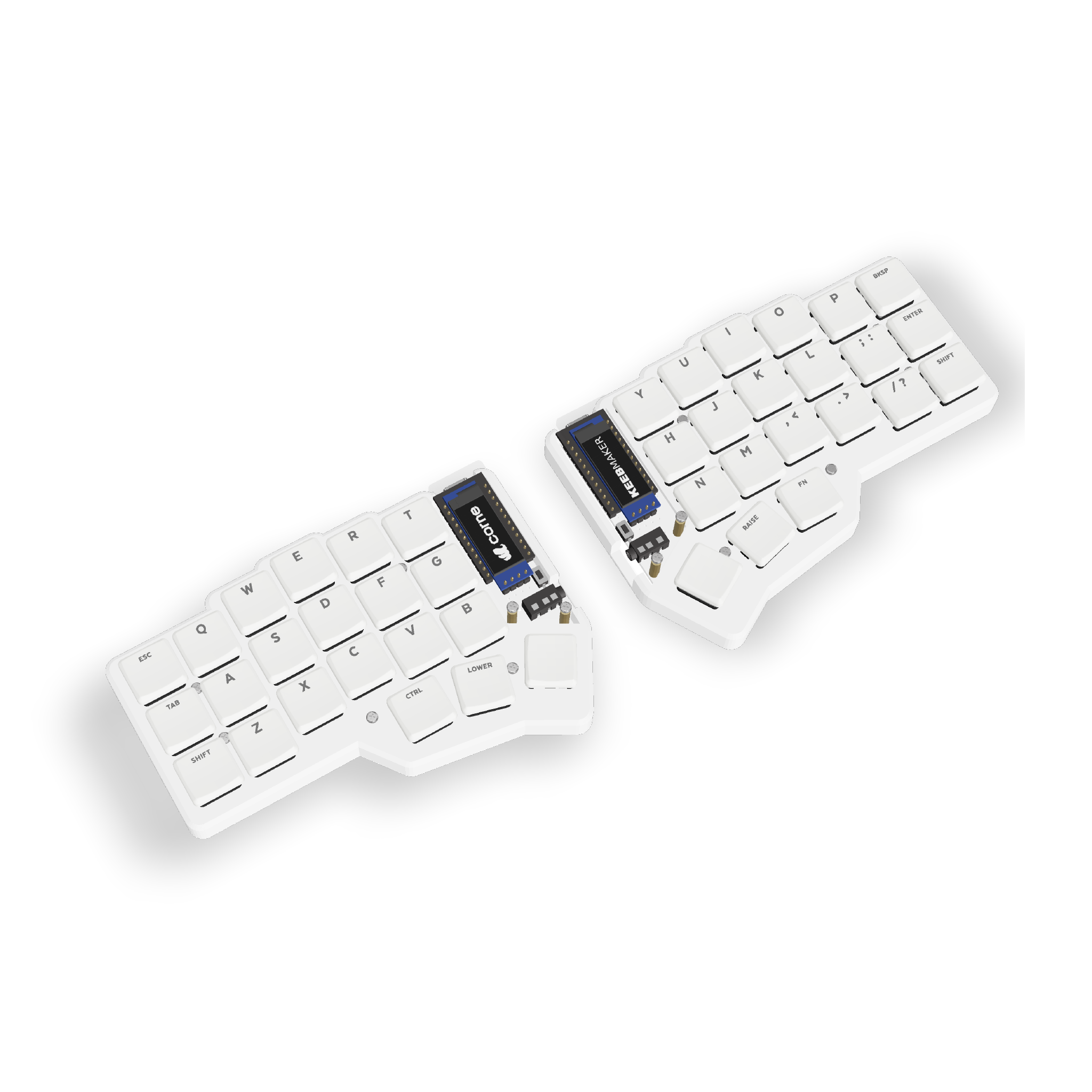
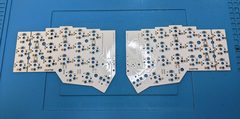
- Corne PCBs x2
- Micro-controllers x2
- Controller Pins x48
- Diodes x36-42
- Kailh Switch Hot Swap Sockets x36-42
- TRRS Jacks x2
- Reset Buttons x2
- TRRS Cable x1
- Key Switches x36-42
- Keycaps x36-42
Optional
- Keyboard Case x1
- Controller Hot Swap Headers x48
- OLED Screens 2
- OLED Pins x8
- OLED Hot Swap Headers x8
- OLED Covers and Hardware x2
- SK6812 3535 LEDs x12
- SK6812 Mini-E LEDs x36-42
Firmware
The KeebMaker Corne uses the standard Corne firmware. You can get started with the default Corne firmware found in the QMK repository, or the VIA firmware available for download here.
We recommend that you flash your controllers before ever touching them with a soldering iron to ensure that they are working properly. Once you have confirmed that your controllers are flashed and ready to go, you can commence soldering.
Soldering
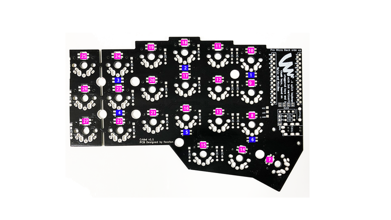
The KeebMaker PCBs are not reversible. There is one left half, and one right half. Make sure that you see silk screens on the side of the PCB you are applying solder to and you’ll be sure that you are soldering the correct side.
Pro tip!
There are many hobbyists on forums across the web that will caution you to use as low temperatures as possible when soldering keyboard components. We do not recommend following this advice.
Prolonged exposure to heat is actually more damaging to keyboard components than brief high temperatures. A lower temperature will require you to press your iron against your PCB for longer before the solder will flow. Not only can this burn out your components, but it makes soldering more difficult, in general.
We recommend a soldering iron temperature of 400° C, even for LEDs. This high temperature will allow you to flow your solder much quicker and be more precise. The key to not burning out your PCB components is to be quick! If you don’t allow your iron to press against your PCB for longer than a couple seconds you're going to be fine.
Diodes
Soldering SMD diodes is pretty straightforward. The most important thing to remember here is that diodes have a specific orientation that they need to be soldered in. You’ll probably have to look really closely at your diodes to see, but there should be a thin white line on each one. You need to make sure that this thin white line is lined up with the silkscreen marking on the PCB when you solder it, otherwise your keystrokes won’t register when you begin typing! If you are having trouble seeing the white line on your diodes, make sure you have really good lighting and try looking under a magnifying glass.
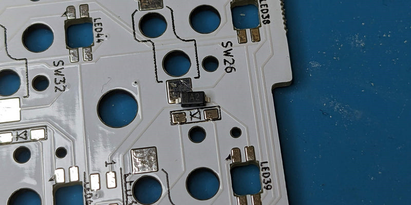
Each Diode gets soldered to the PCB via two pads. To begin, we’re going to tin (apply a bit of solder to) just one pad of each diode receptacle on the PCB.
After each diode receptacle has one pad tinned, we’re going to start soldering the diodes. For this part, you can put your solder down and grab your tweezers. What you’re going to do here, is grab a diode with the tweezers and set it down on the diode receptacle, so that one leg of the diode is gently pressing against that tinned pad that we prepared earlier. While holding the diode in one hand with your tweezers, you are going to press the tip of your soldering iron against the tinned pad in order to reflow the solder. Once that solder has been liquified again, you are going to slide the leg of the diode into the solder. Once you get that diode leg into the reflowed solder, remove the tip of your iron and the solder will harden, securing your diode to the PCB. Repeat this process for each diode on your PCBs.
Once you have secured each diode to your PCBs, you can then go back through with your soldering iron and solder the second leg on each diode to the PCB.
Switch Hot Swap Sockets
There are a couple ways to solder your hot swap sockets. Choose the one that you are most comfortable with.
The first option is to tin each pad with solder before ever seating the switch sockets. Once you’ve tinned both pads of a switch socket receptacle, you can seat the switch socket. After it’s seated, simply press your iron into one metal leg of the switch socket until the solder underneath it melts. The switch socket leg should slide into the liquified solder, pressed by the weight of the soldering iron tip. As soon as it does, you can remove the soldering iron. Repeat this on the other side, and you’ve got a soldered switch hot swap socket!
The second option is to simply seat the hot swap socket into the receptacle, press your iron against the leg and the pad, and apply solder.
Reset Switches
Simply insert your reset switches from the top, down. Then flip your PCB over and solder each of the two legs.
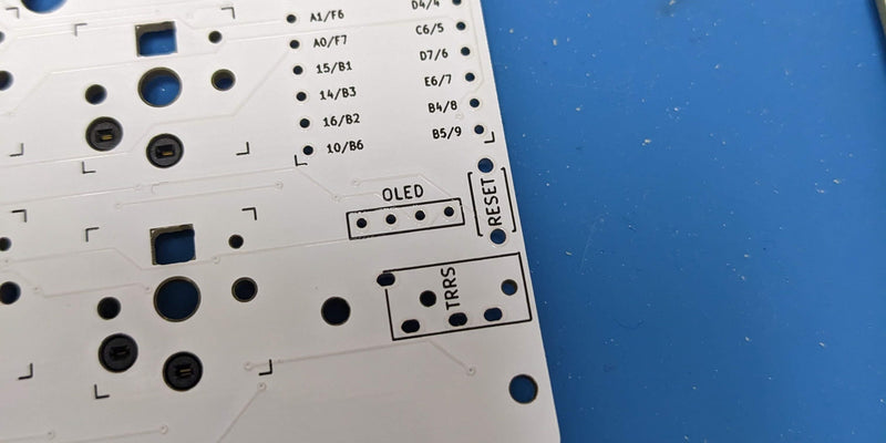
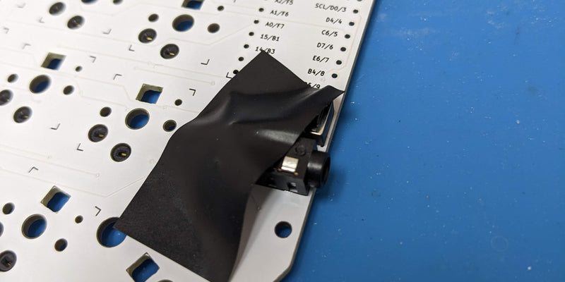
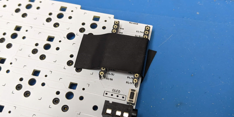
TRRS Jacks
Insert your TRRS jacks through the PCB from the top, down. If you secure them with a bit of tape, they won’t fall out when flipping your PCB over. Flip your PCB over and solder each of the 4 legs on each TRRS jack.
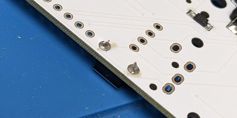
Controller Headers
If you are hot swapping your controllers, you'll now be soldering the hot swap headers. If you aren't hot swapping your controller, you'll be soldering the standard headers that come with your controllers.
Place your headers into the correct holes, top-down. Secure these with a bit of tape, and flip your PCB over.
At first, you should solder only one pin on each half.
Once you have soldered one pin, you can then remove the tape from the top side and check how straight and flush your headers are. If you need to adjust the position of your headers, it should be easy to accomplish by doing the following.
- Use one hand to pinch the PCB and the header
- While being careful not to touch the pin you are about to heat up, use your other hand to reflow the solder on the one pin that is holding your header to the PCB.
- Once the solder has reflowed, use your fingers that are pinching the header and the PCB, to move the header into a straight and flush position.
- Once satisfied, remove the iron from the PCB and let the solder harden again.
Once you are sure that your headers are straight and flush, you can finish soldering each pin.
Caution!
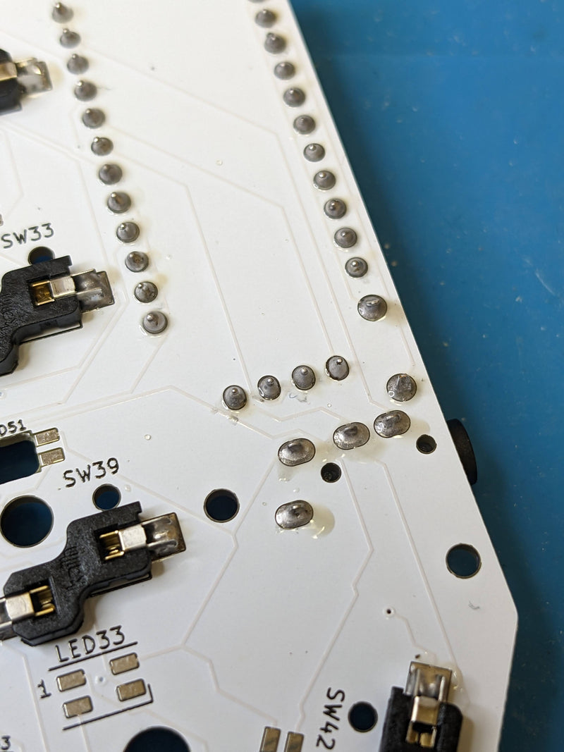
Make sure that when soldering these pins, you are not creating any solder bridges. If any of your header pins become connected by solder, your keyboard will not function properly.
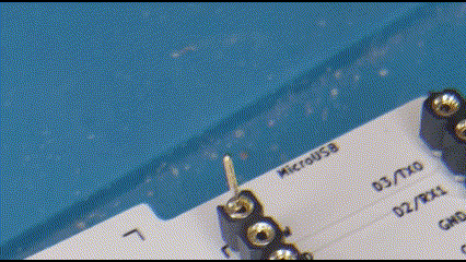
OLED Hot Swap Headers
Soldering OLED headers is just like Controller headers, just in a different spot on the PCB, obviously.
You don't technically need headers for your OLED screens, but it makes them sturdier, and hot swappable. If you'd prefer though, you can solder the OLEDs directly into the PCB using diode legs once we get to them.
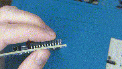
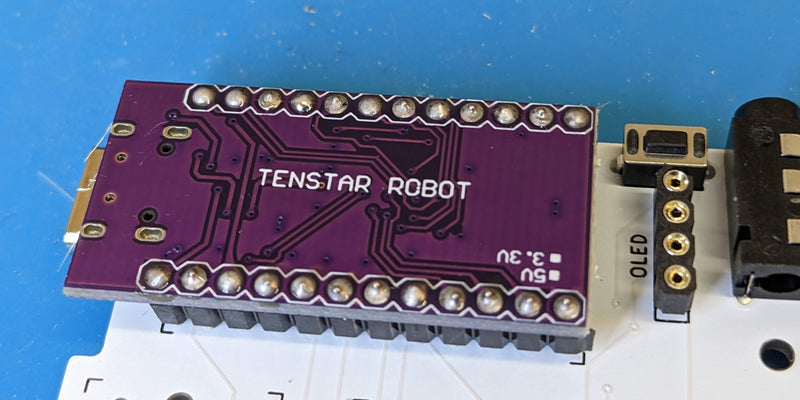
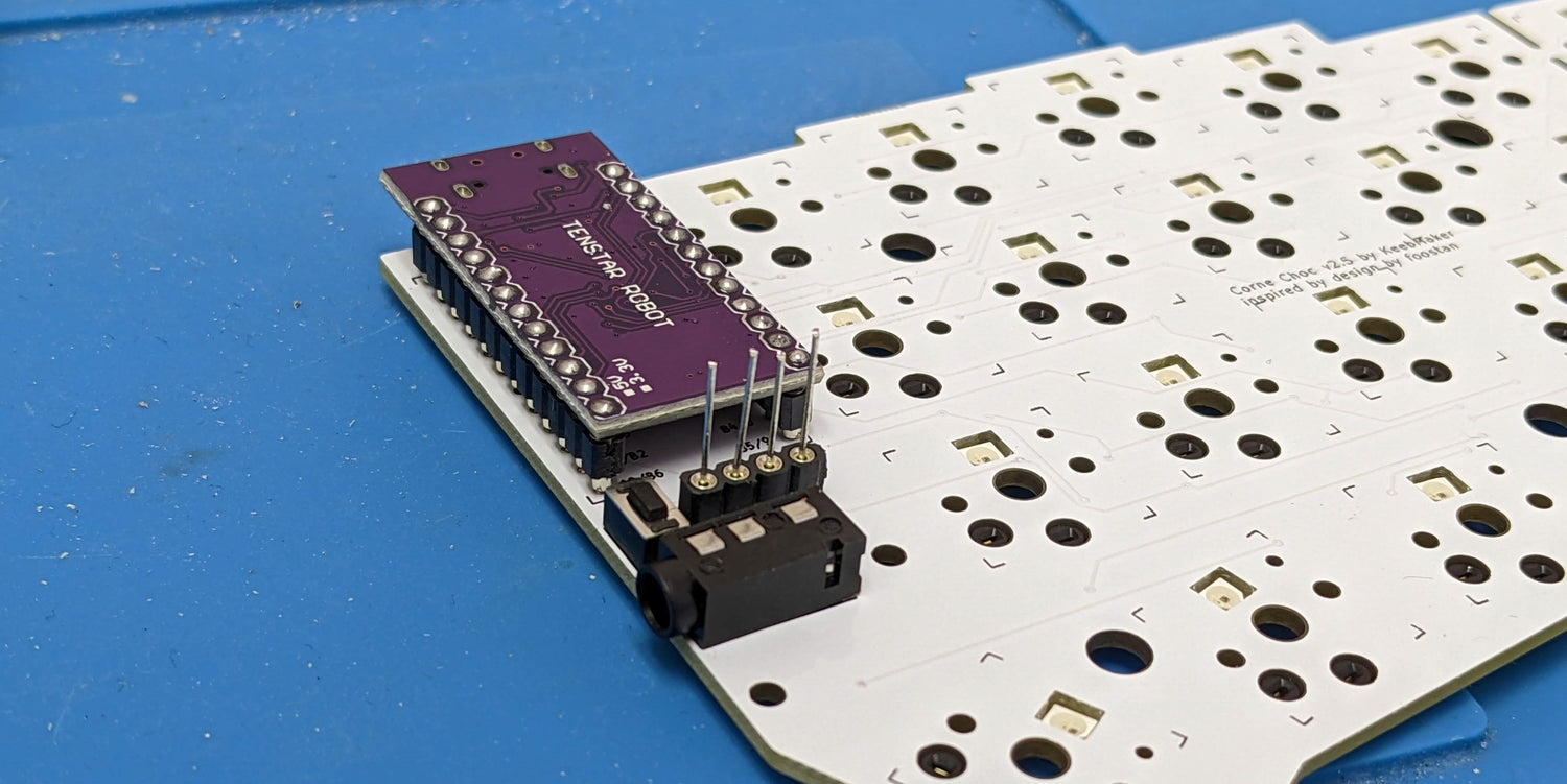
Micro-Controllers
Make sure that your PCB is flipped top-side up again. If you are hot swapping your controller, it's time to insert our controller pins into the controller headers. If you aren't hot swapping your controller, you can jump straight to socketing your controller.
When inserting hot swap pins, be careful not to bend them as they are inserted into each header socket. You’ll want to apply light, consistent force with the back edge of your tweezers until you feel the pin gently slip into place.
After you have seated all your controller pins, slip your controller face down onto the pins. There should be a perfect amount of pin poking out the top for you to solder. Remember not to let your iron sit for longer than a second or two at a time as you solder each pin.
Caution!
Make sure that when soldering these pins, you are not creating any solder bridges. If any of your header pins become connected by solder, your keyboard will not function properly.
Take A Break For Testing
This is a good time to take a break from soldering and make sure that everything is in good order. Ideally, you will have already flashed your controllers at this point, as recommended above.
Put your soldering iron down and plug your two keyboard halves together using your TRRS cable. Next, plug your keyboard into a computer using a USB cable. Since you don’t yet have switches in your PCB, you’re going to need to use your tweezers to test each key press. Open up a key-testing software of your choice (or notepad), and begin touching each switch socket with your tweezers like so.
Your keyboard should register a keypress for each switch socket you do this on.
Heads Up!
You likely have a few keys on your keyboard that are set as layer toggles. These switches will likely not register as a keypress by itself. If the rest of your keys are all working, you’re probably good to go on these. If you really want to make sure these are working, you can grab a second pair of tweezers or a bent paper clip, and actuate the toggle with one hand, and a different key with the other. If the keypress registered is different based on whether or not you are holding down that layer toggle, this means it’s working.
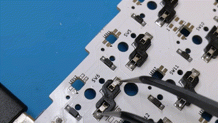
LEDs
LEDs on the Corne are wired in series. This means that each LED is dependent on the LED before it. Because of this, you should solder your LEDs in the following order, so that you will be able to test as you go.
(Image credit: Foostan)
Underglow LEDs
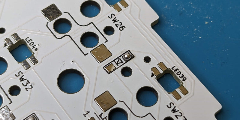
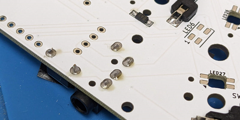
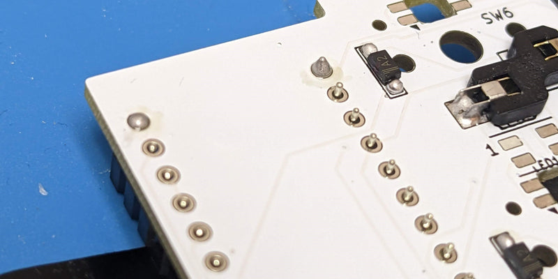
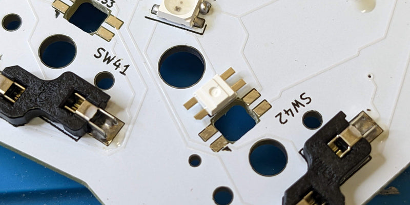
Underglow LEDs have a specific orientation that they must be soldered in. When soldering LEDs, make sure that the corner of the LED with the notch in it is lined up with the right-angle marking on the silkscreen.
Underglow LEDs are soldered in a similar fashion to diodes. To begin, we’re going to tin just one pad of an underglow LED receptacle on the PCB.
After that receptacle has one pad tinned, we’re going to start soldering the underglow LED. For this part, you can put your solder down and grab your tweezers. What you’re going to do here, is grab an LED with the tweezers and set it down on the LED receptacle, so that one pad of the LED is gently pressing against that tinned pad that we prepared earlier. While holding the LED in one hand with your tweezers, you are going to press the tip of your soldering iron against the tinned pad in order to reflow the solder. Once that solder has been liquified again, you are going to slide the pad of the LED into the solder. Once you get that LED pad into the reflowed solder, remove the tip of your iron and the solder will harden, securing your LED to the PCB.
After your underglow LED has had one pad soldered to the PCB, you can go back and solder the remaining pads. To do this, you’ll want to lightly press your iron against the PCB pad and the exposed part of the LED pad for just a second, before applying your solder.
Note: You definitely don't need as much solder as is shown in these gifs. Using too much solder can cause bridging, which will prevent your LEDs from working.
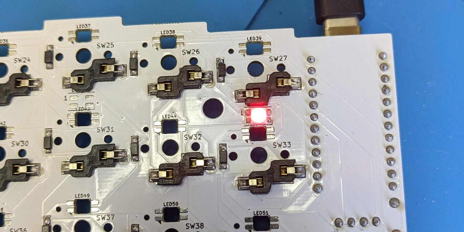
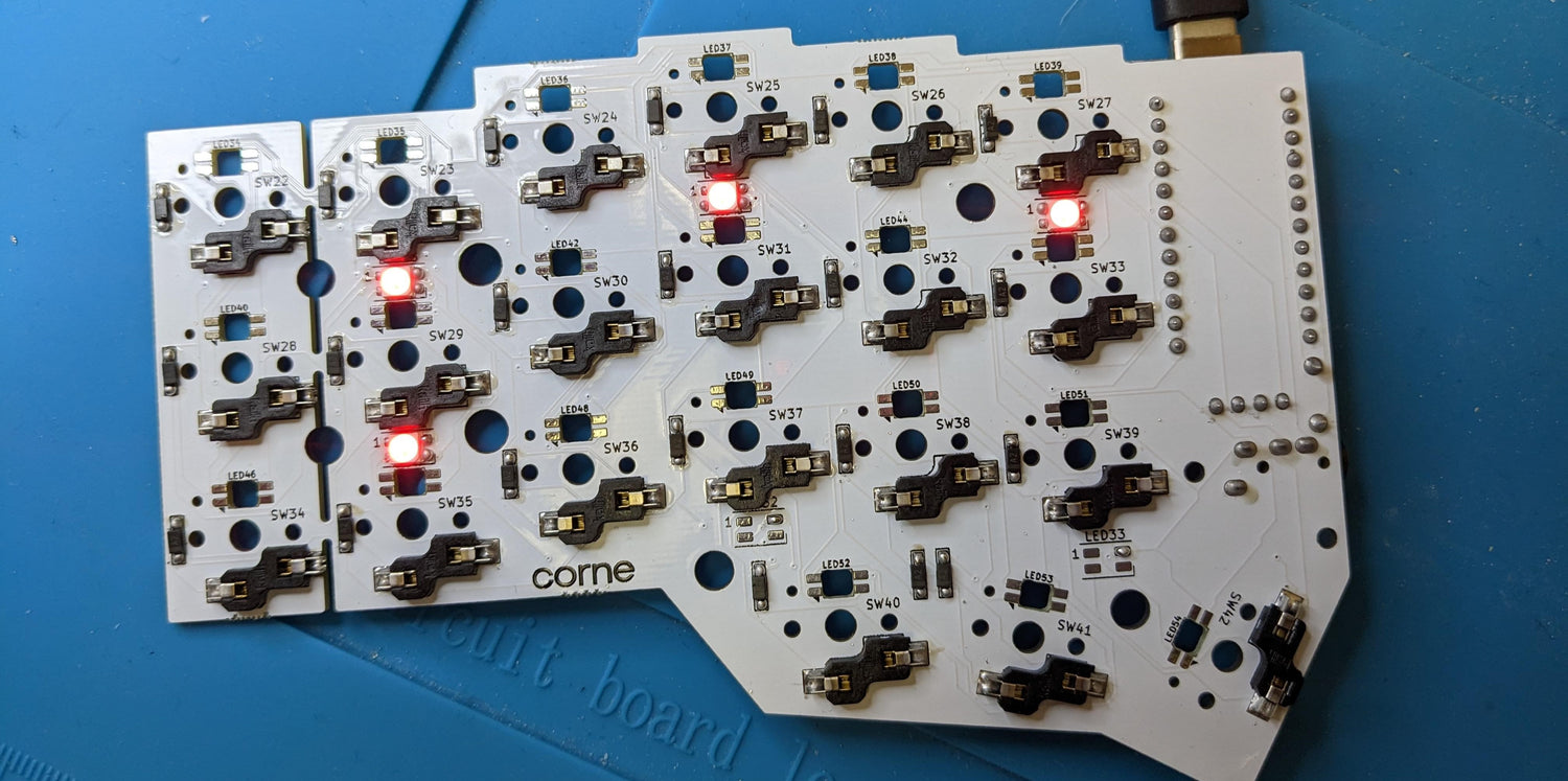
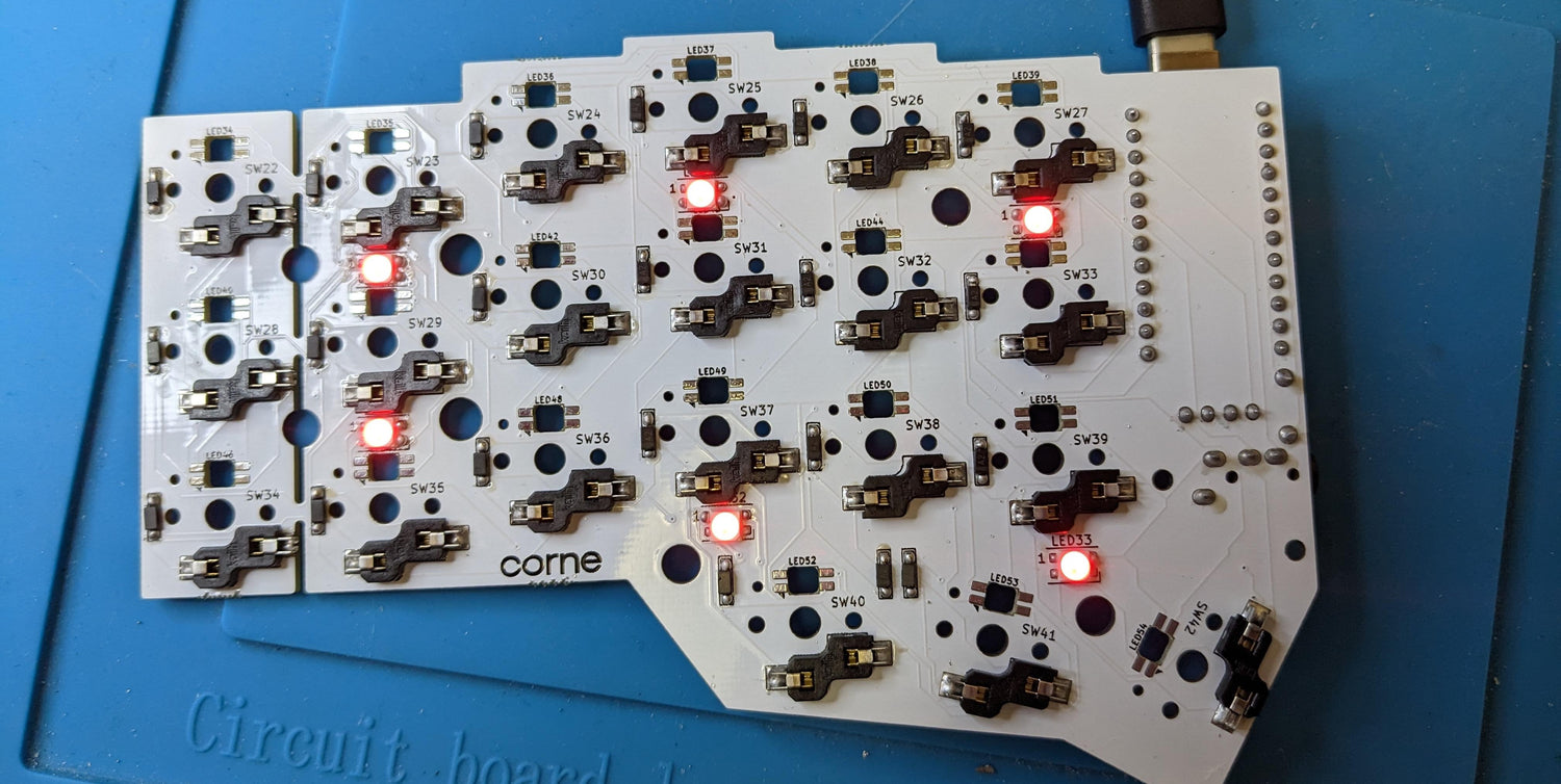
We recommend taking LEDs one at a time to get started. Solder all 4 pads of the LED to the PCB, then plug in your keyboard to make sure that the LED lights up. If it does, you are good to move onto the next one. If it doesn’t, you’ll need to get that LED working before moving on.
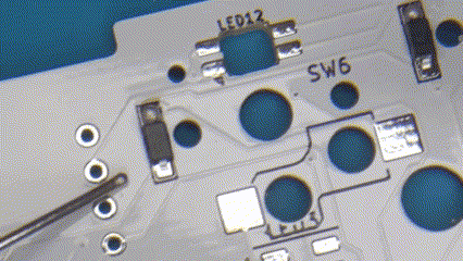
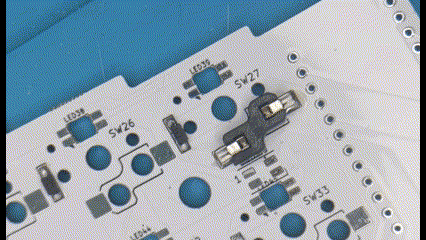
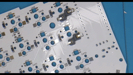
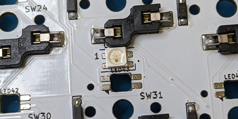
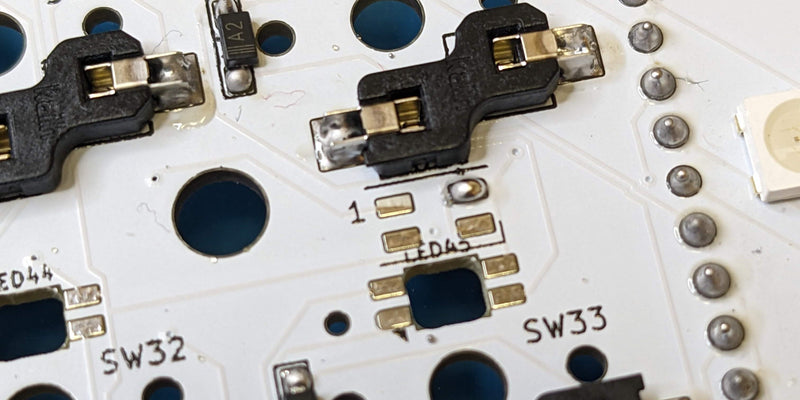
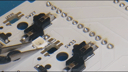
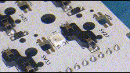
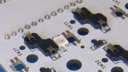
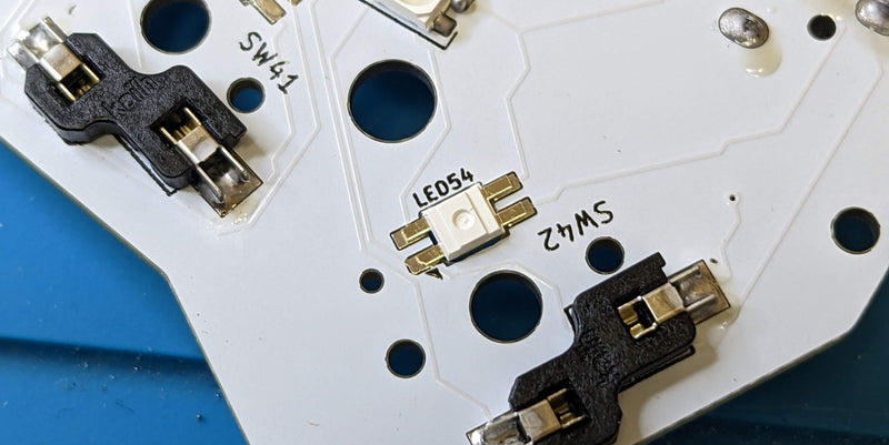
Per-Key LEDs
Once you have all the underglow LEDs soldered, it’s time for the per-key LEDs. Per-key LEDs also have a specific orientation in which they must be soldered. When soldering, make sure that the LED leg with the clipped end lines up with the little triangle marking on the PCB silkscreen.
Soldering these per-key LEDs is a piece of cake. Simply drop your LED face-down into the LED receptacle and solder the 4 legs onto the pads.
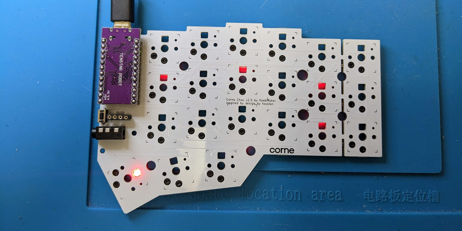
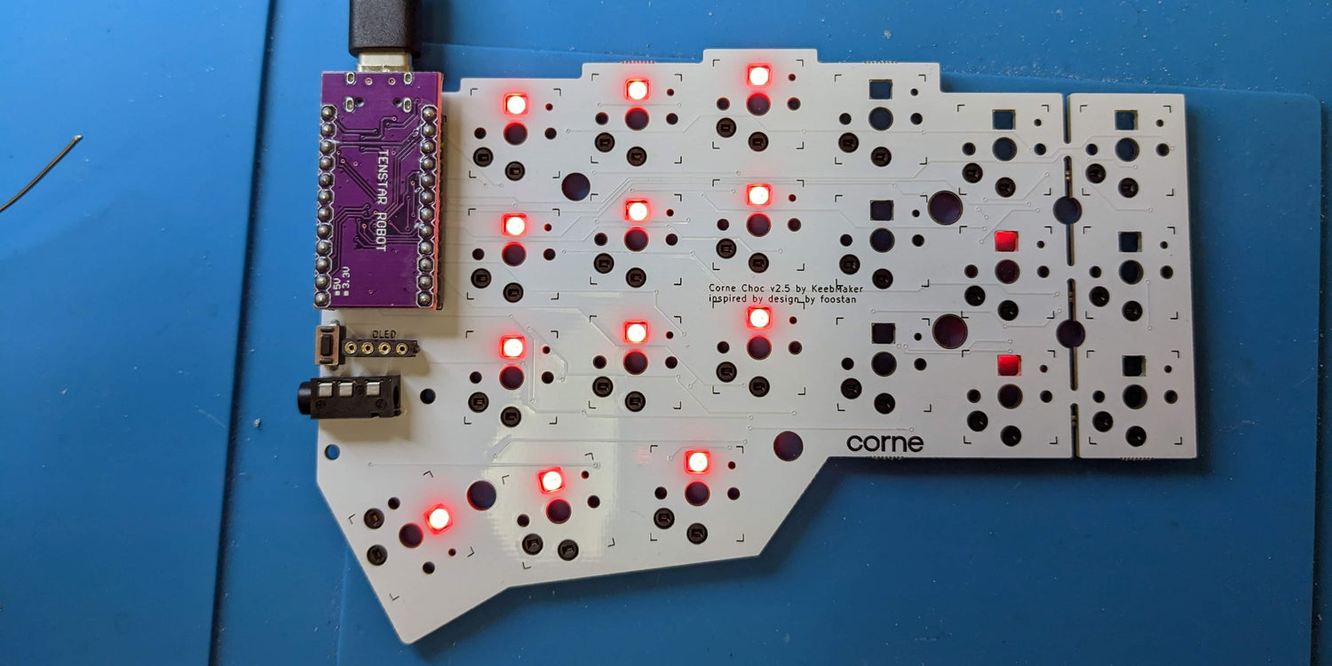
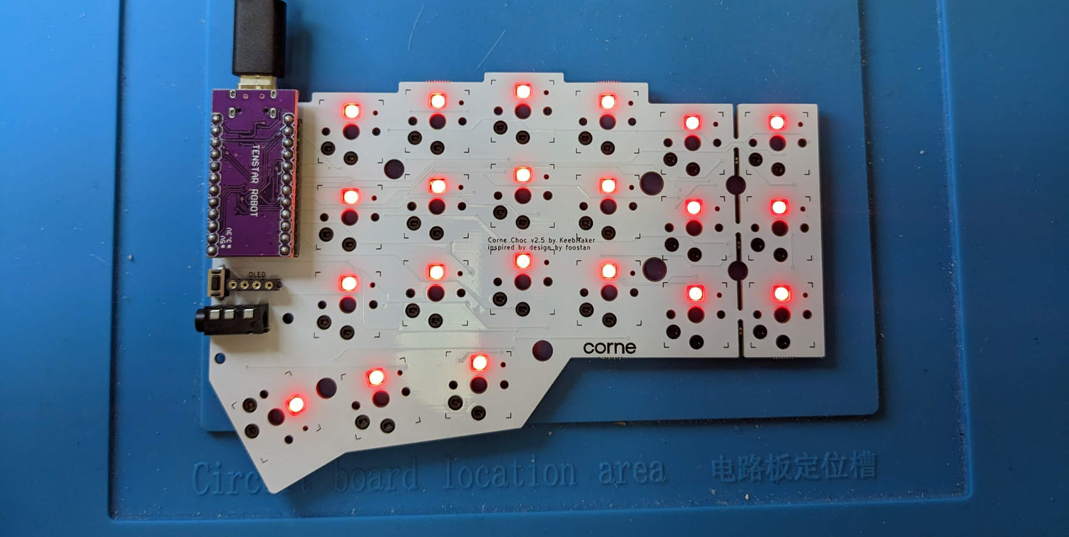
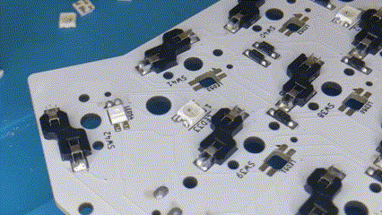
Once again, we recommend taking these LEDs one at a time to get started. Solder all 4 pads of the LED to the PCB, then plug in your keyboard to make sure that the LED lights up. If it does, you are good to move onto the next one. If it doesn’t, you’ll need to get that LED working before moving on.
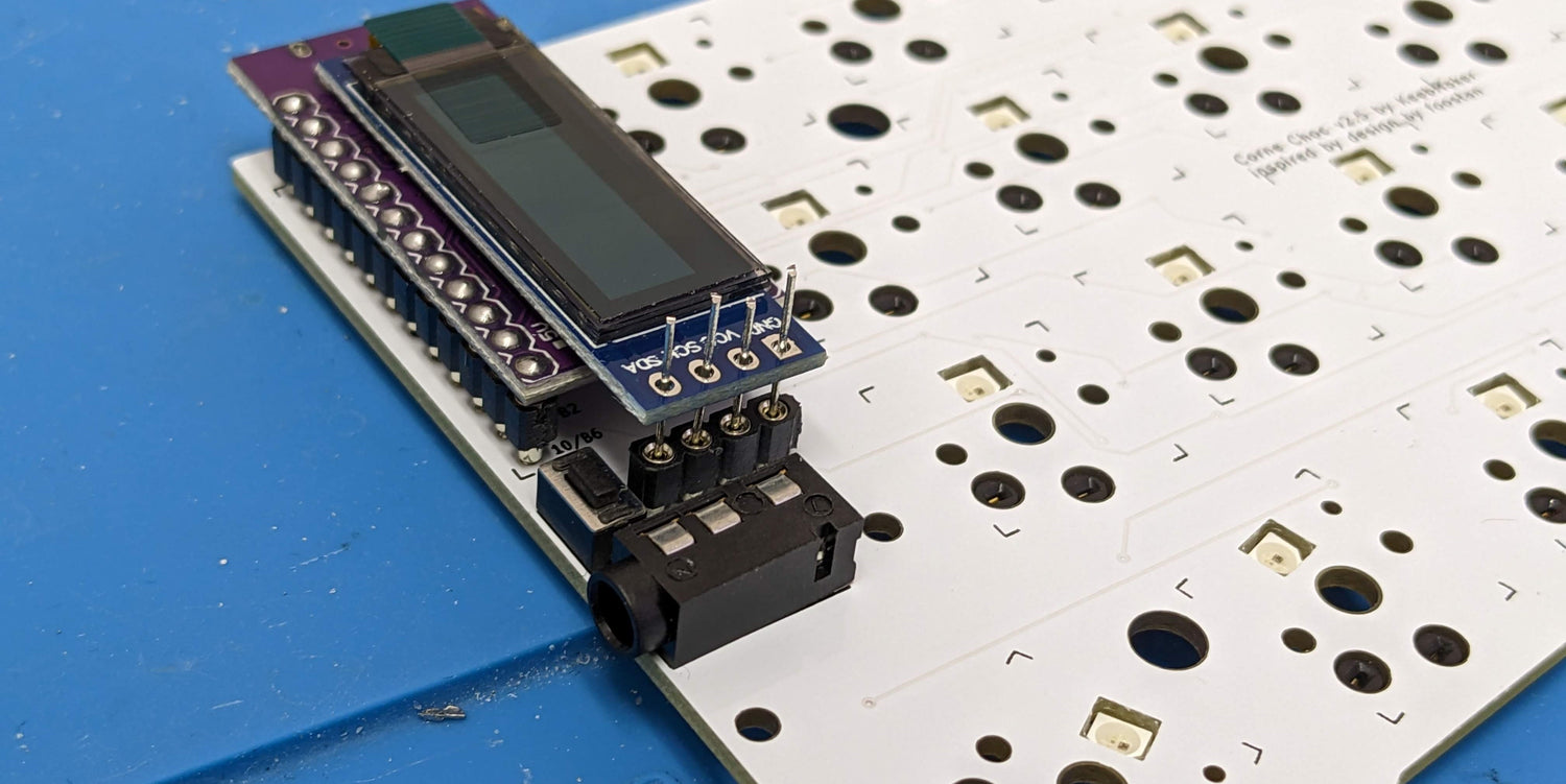
OLED Screens
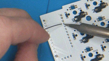
Now that you've come this far, OLEDs are going to be a piece of cake. If you're hot swapping your OLEDs, you'll need 8 through-hole diode legs for this. Otherwise, you can just use the headers included with your OLED screens.
If you're using diode legs insert a leg into each sip socket. Once you've done this, you can slide the OLED screen over the legs and solder. Once you're finished, you can use flush cutters to trim the excess wire sitting above the OLED.
OLED Cover Stand Offs
If you have OLED covers to install, now is the time to install the stand-offs. Insert screws into your PCBs from the bottom, then screw a stand-off onto each.
You don't want to install the actual cover just yet. This will be easier to do after you have finished putting your switch plate on.
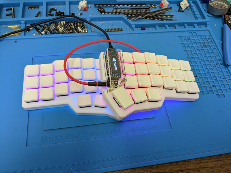
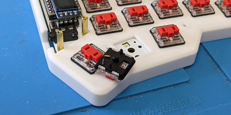
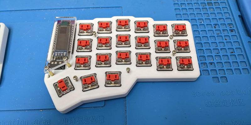
Switch Plate and Switches
Once you’ve got all the components soldered onto your PCB, it’s time to put it into your case and get some switches in it! Some people find that it helps to insert several switches into the plate first, and then press the plate with the switches into the PCB.
Once you have all the switches in, we recommend that you take another quick break for testing! It’s fairly easy to bend switch legs when inserting them into your PCB, so you’ll want to plug in your keyboard and make sure all your switches are registering before completing the assembly of your case. If any switches are not working, pull the switch out and make sure the legs aren’t bent before putting it back in.
Case Assembly
You’re now ready to screw your case together. You’ll want to do this before putting on your keycaps. There are small holes in your case plates that line up with threaded inserts in the bottom of your case. Simply insert screws into these holes and use a screwdriver to drive them in. You shouldn’t need to use much force.
Keycaps
Once your case has been fully assembled, it’s time to pop on your keycaps and get typing!